
 |
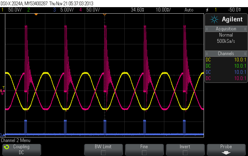
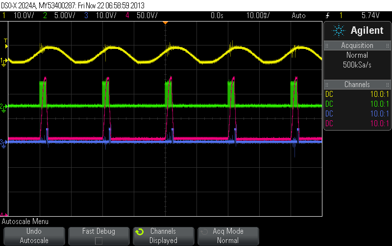
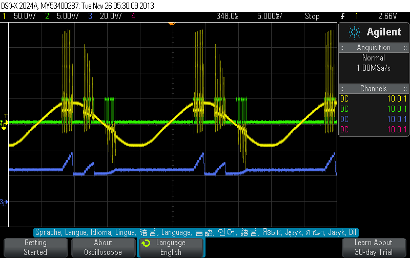
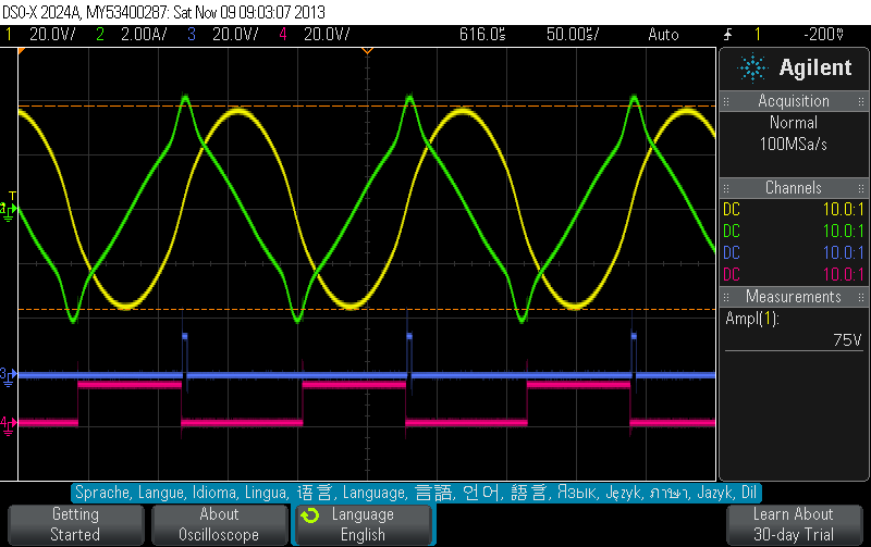
The following scope shots shows the result. The yellow curve is the voltage over the primary, the red curve the voltage over the secondary.
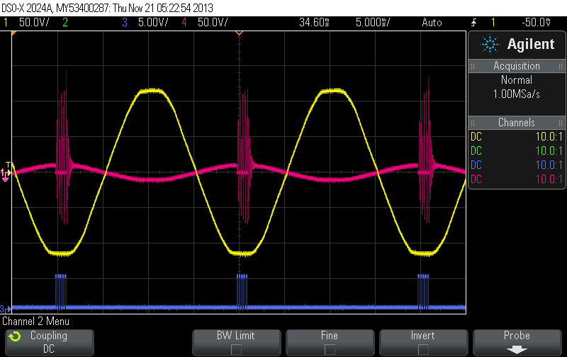 |
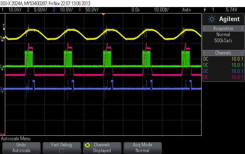
We zoom into the ringing.
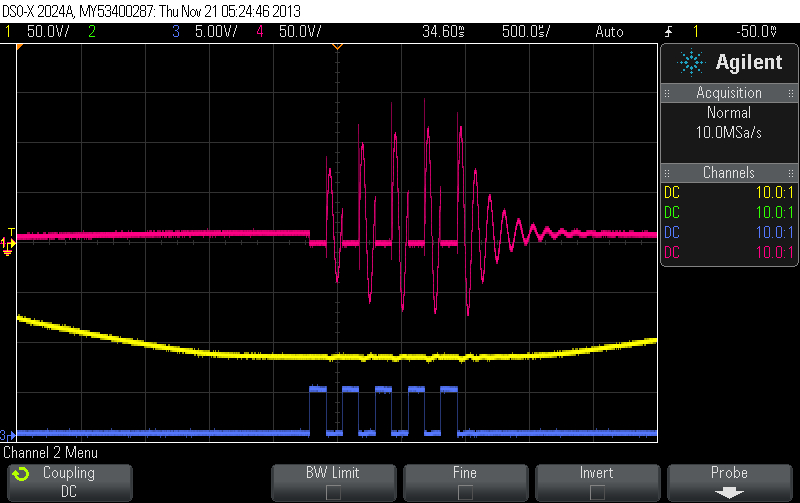 |
It can clearly be seen that we get no CEMF - which means the the AC MOSFET switch does a good job - and that the ringing is caused by BEMF when the AC MOSFET switch is switched off. We use a primary and secodary with equal number of turns now.
 |
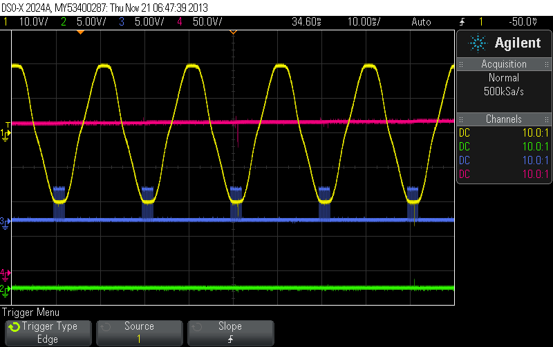
The capacitor is charged to 200V due to the ringing with an input voltage of 43V. But it takes eons for the cap to reach this value! :-(
 |
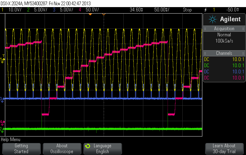
We insert a MOSFET between the FWBR and the cap now and switch this one on only for the coil shorting window to isolate the coil from the cap for the load dumping process. We add an additonal MOSFET that discharges the cap into a load. However, we switch off this discharge cap when a certain voltage in the cap has been reached (downwards) meaning that we do not completely discharge the cap but keep a specific voltage level to make sure the cap is charged by ringing only. We can no longer measure the AC ringing now since the AC legs of the FWBR are floating now (we grounded the DC minus of the FWBR). We instead measure the voltage in the cap.
With 83V AC (8.6W) input we get
 |
The 40uF cap is charged up to 225V every 2.1s and then discharged to 65V. This corresponds to an output wattage of 0.44W! :-(
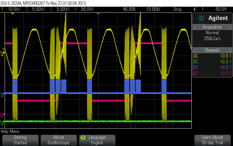
We replace the 40uF cap with 3uF and use shorter cables to reduce inductance. This gets us
 |
The output wattage is neglible!
We replace the self-wound transformer with an industrial 240V -> 220V (2.5kVA) transformer and get lots of ringing on the primary now and thus lots of additonal firing pulses in spite of the RC snubber in the detection circuitry.
 |
The output wattage of 0.86W is still negligible! :-( We go back to 40uF and do some spike snuffing in the zero-crossing detection and finally get some measureable output.
 |
The 43uF cap is charged to 287.5V and then discharged into a load (down to 155V) every 20ms. This corresponds to an output wattage of 63W. The input wattage into the system is 74W. 11W are lost in the transfomer.
 |
We add 20uF capacity and get
Capacitance: 63uF
Start Voltage: 265V
Stop Voltage: 165V
Output: 68W
Input: 84W
We add another 20uF capacity and get
Capacitance: 83uF
Start Voltage: 300V
Stop Voltage: 200V
Output: 104W
Input: 128W
 |
We use a differen circuit now
*****
and get for 1uF.
 |
AC series cap approach
We connect an AC cap and the AC leads of a FWBR in series to the secondary of a transformer coil. We short the transformer coil with an AC MOSFET switch. We connect a DC cap to the DC leads of the FWBR and discharge that into a load with vi a MOSFET.The following circuit is connected to the primary (or secondary) and is reponsible for generating the MOSFET gate signals.
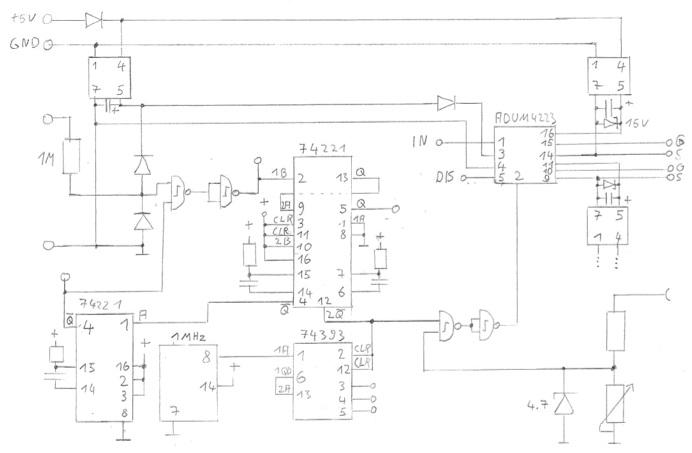 |
The upper gate signal is for the AC MOSFET switch the lower for the discharge MOSFET. The lower left one-shot (74221) suppresses a retrigger (due to transients) for a complete cycle (full wave lengths). WIthout this retrigger suppression we would end up with something like the following:
 |
The 74221 in the middle contains two one-shots. The first causes an adjustable delay. The second opens a window for shorting pulses (AC MOSFET switch).
Tertiary shorting at current peak
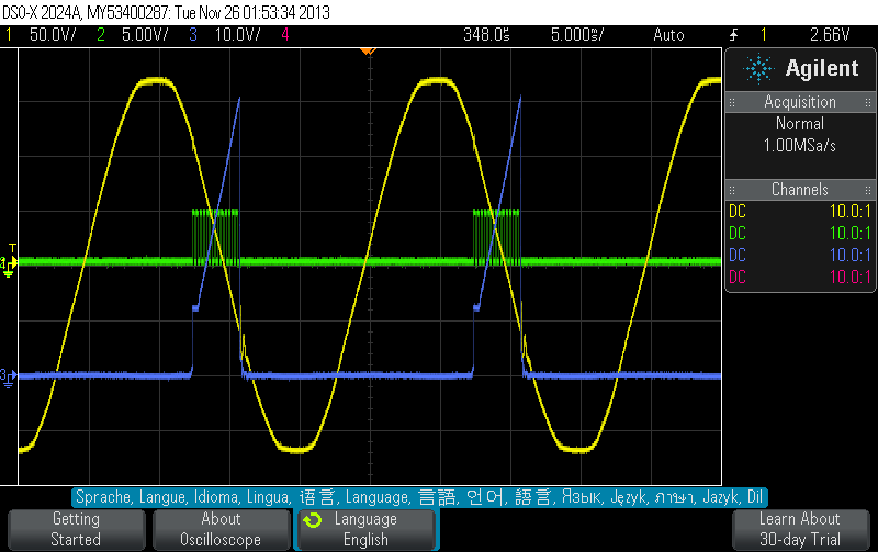
The idea is to connect a voltage zero-crossing detection circuit to the tank and short the tertiary coil for a brief moment (optionally a couple of times) at current peak and let it go again before the core gets out of saturation.
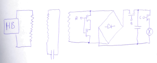 |
We eed to generate three signals for this. A is pulsed in a window directly after voltage zero crossing. MOSFET B is active only in this small window to prevent charging the DC cap with the normal sine wave and thus detuning the tank. MOSFET C is switched on whenever B is off.
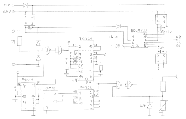 |
A PIN1 as now connected
B 2Q
C 2Q_
 |
News
| 23.04.2023 | Cassiopeia 2.9.0 released |
| 05.10.2022 | Cassiopeia 2.8.3 released |
| 29.09.2022 | Cassiopeia 2.8.0 released |
| 08.07.2022 | Cassiopeia 2.7.0 released |
| 14.04.2021 | Cassiopeia 2.6.5 released |
| 10.02.2021 | Cassiopeia 2.6.1 released |
| 26.06.2015 | Word Processor Comparison |
| 24.06.2015 | Updated Documentation |
| 23.06.2015 | Cassiopeia Yahoo Group |
| 18.06.2015 | Advanced Data Security |
| 11.05.2015 | Cassiopeia Overview |
| 08.05.2015 | Exporting to files |
| 14.05.2013 | LaTeX and HTML Generation |
| 08.05.2013 | Example Paper released |
| 26.04.2013 | Co-editing in a workgroup |
| 16.04.2013 | Equation Editor Quick Reference |
| 12.04.2013 | Equation Editor |
| 04.04.2013 | Links and Bibliography |
| 01.04.2013 | Books |
| 30.03.2013 | Documents |
| 28.03.2013 | Simulations |
| 16.03.2013 | 2D Graphs |
| 10.03.2013 | Symbolic Algebra |
| 08.03.2013 | Getting Started |
| 07.03.2013 | Installation and Setup |
White Papers
| 13.10.2015 | 01 Writing documents |
| 15.10.2015 | 02 Using the equation editor |
Youtube
| 08.07.2022 | Installation & Getting Started |
| 14.04.2021 | Animating Wave Functions |
| 26.01.2016 | Keystroke Navigation |
| 22.10.2015 | Equation Editor Demo |
| 19.06.2015 | Equation Editor Tutorial |
| 10.06.2015 | Sections and Equations |
| 09.06.2015 | Getting Started |
| 09.06.2015 | Damped Oscillations |
| 29.05.2015 | Solving equations |
| 13.05.2015 | Privileges and Links |
| 19.06.2013 | Magnetic Field |
| 14.06.2013 | Creating Documents |
| 10.06.2013 | Vector Algebra |
| 30.05.2013 | Differential Simulations |
Contact
Smartsoft GmbH Advanced Science Subdiv.Support: support@advanced-science.com
