
 |
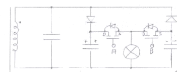
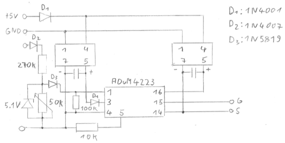
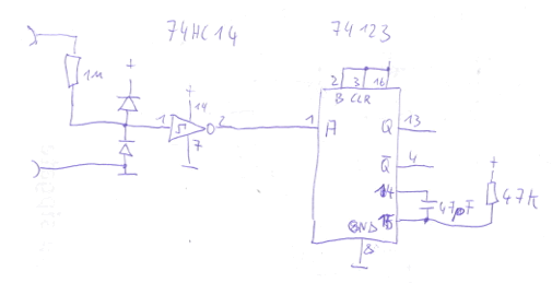
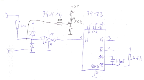
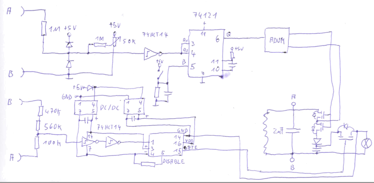
The signals A and B are generated with the following circuit (we need two instances of it):
 |
Testing the circuitry
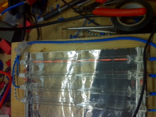
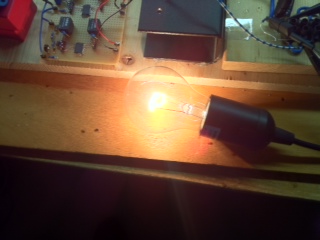
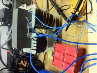
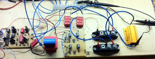
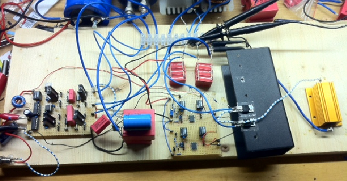
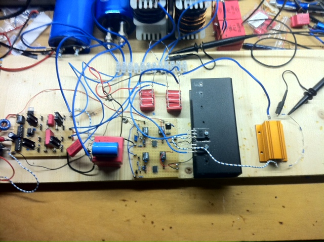
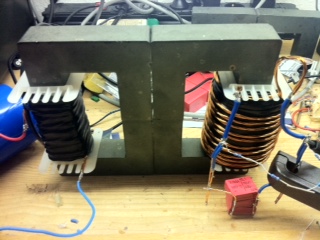
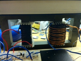
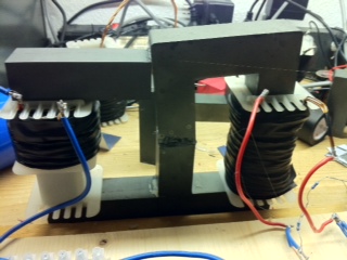
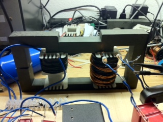
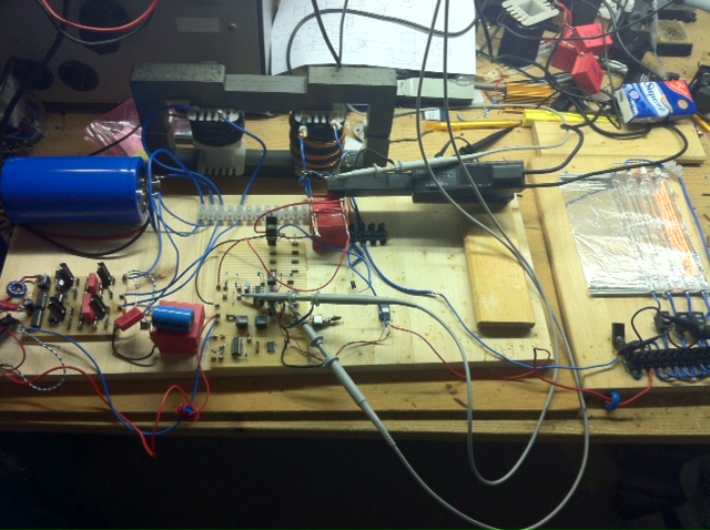
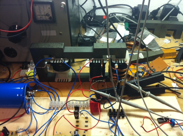
A realization of this setup looks as follows.
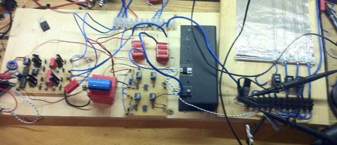 |
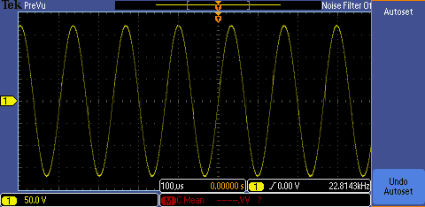
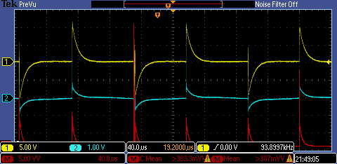
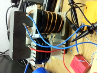
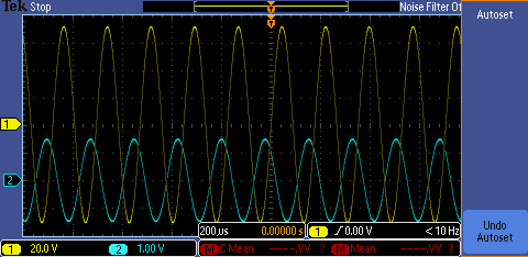
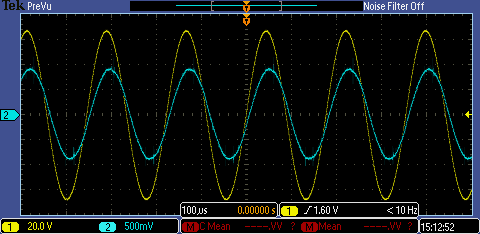
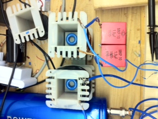
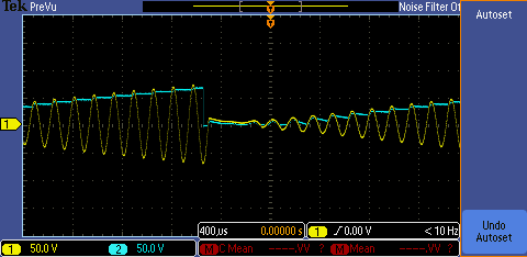
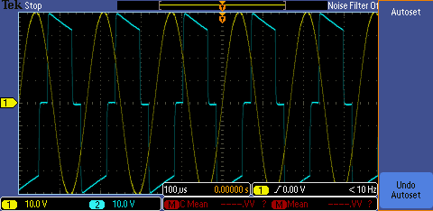
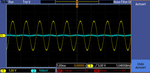
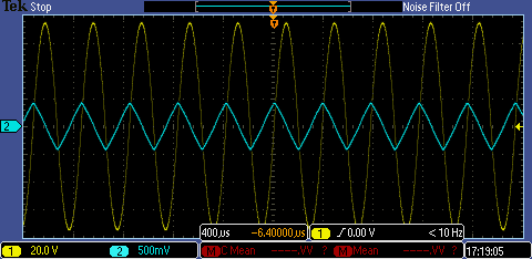
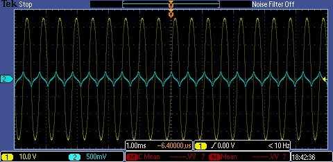
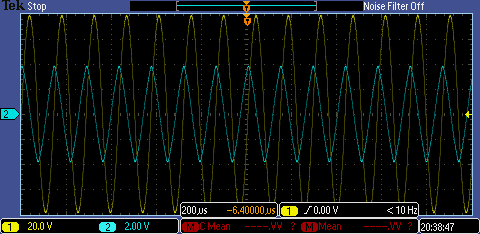
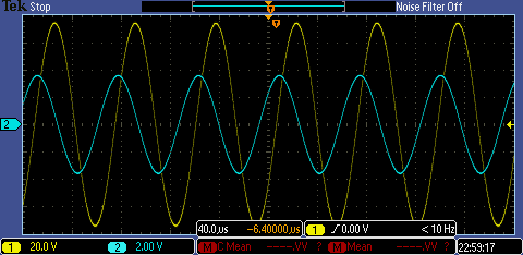
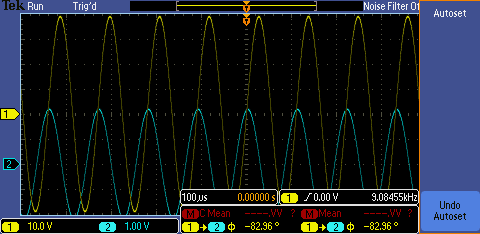
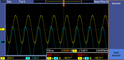
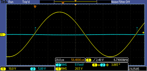
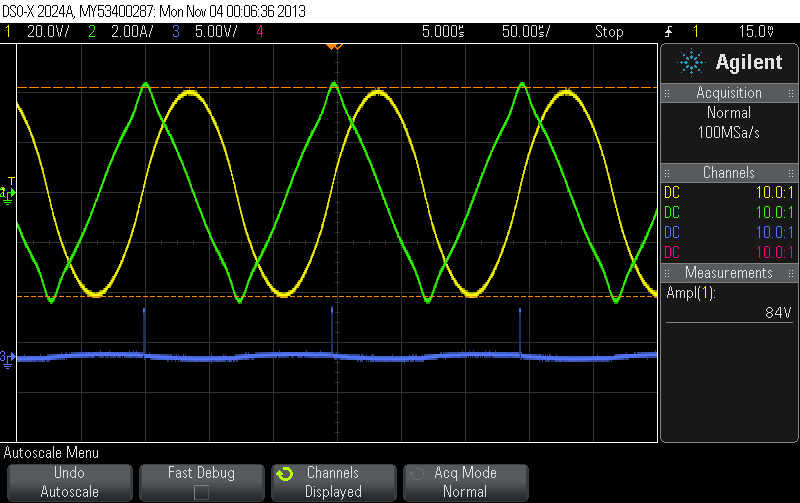
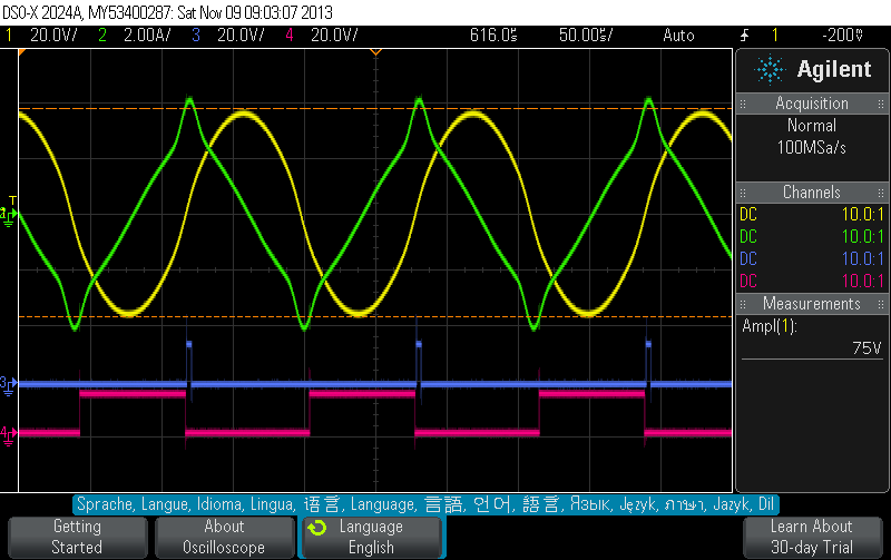
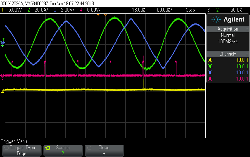
The PCB on the lower left carries the H-Bridge (IF3205). In the middle you can see the two 300nF DC caps (actually 3 x 100nF in parallel). The PCB below the caps provides the peak detection circuit and generates the gate signals (isolated) for the two MOSFETs on the black cooling unit. The peak detection circuit generates the following (floating) signal for the MOSFET gate (blue). The yellow line is the tank voltage.
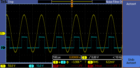 |
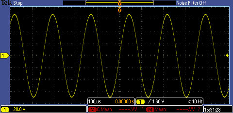
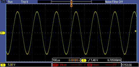
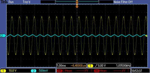
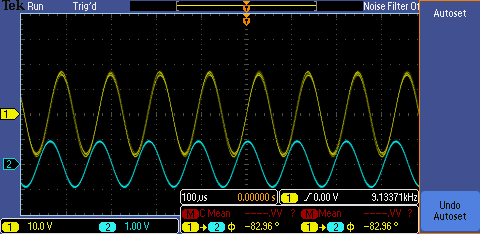
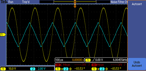
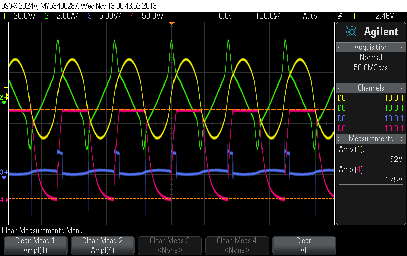
We use 680nF for the AC cap and 300nF for the two DC caps. At an input of 2V/3.5A (7W) to the H-Bridge we get 170Vp oscillations in the tank (no load attached).
 |
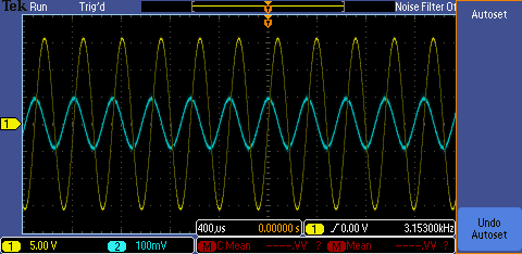
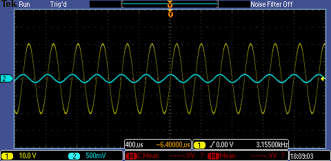
A 680nF cap charged to 170V corresponds to 9.8mJ. The circuit at 7.575kHz does this 15151 times per second. We thus have oscillating power of 148W and thus a Q of 21. We attach a 220V/1000W light bulb as a load now and measure voltage over and current through the load.
 |
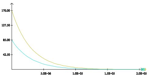
The voltage in a cap attached to a resistor normally decreases according to
 | |
 |
 |
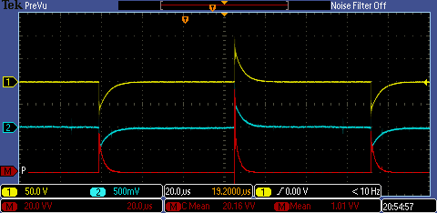
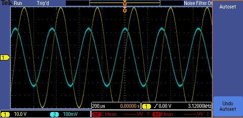
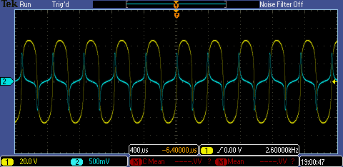
The red line in the above scope shot is a math function multiplying channel A (voltage over load) and B (voltage over 0.1 shunt). We have also added a mean measurement for this product. It shows 1.01VV. Since we measure the current over a 0.1 resistor, we have to multiply this with 10 to get the power out. The output wattage is therefore 10.1W with an input wattage of 12V/1.0A (12W): definitely under unity.
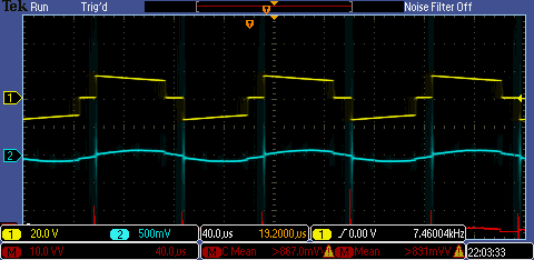
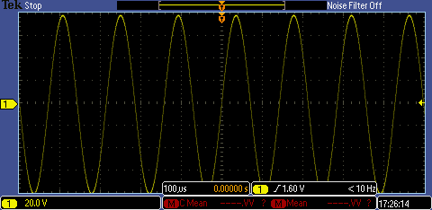
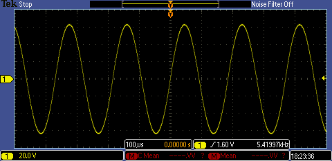
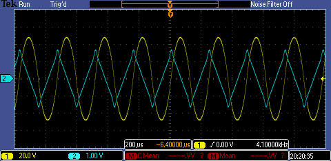
We modify the frequency to find the best resonance with the newly attached load. We find this resonance at 6.8kHz with an input wattage of 12V/2.8A (33.6W) and an output wattage of 33.1W.
 |
This is not too bad. It seems we are loosing only 0.5W in the circuitry. The H-Bridge MOSFETs stay cool. The voltage in the tank is 98.2V (138.8Vp). The 1000W light bulb is glowing as it should at 30W and generates the expected amount of heat.
 |
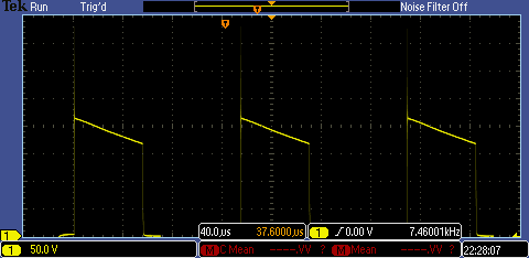
We slightly increase the input voltage and retune the frequency for max peak voltage in the tank. We end up with 13.2V/3.3A (43.56W) input and measuring the load voltage over a 10:1 voltage divider
 |
with a tank peak voltage of 168Vp. The power measurement of the scope becomes unreliable (due to transients). It says > 38.7W, we can only guess.
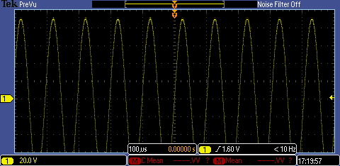
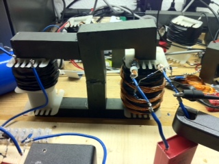
We try to reduce the transient problem by using a 60W light bulb instead (less initial current). We had to reduce the input voltage since our AC voltmeter for the tank voltage reached its maximum at 200V AC. After retuning the frequency for max tank voltage we ended up with an input of 10V/4.6A (46W), a tank voltage of 176V AC
 |
and a reasonably glowing 60W light bulb.
 |
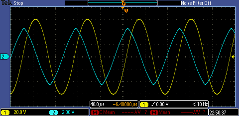
All MOSFETs stay cool. Power measurement with the scope math function still fails. However., we can see the voltage drop in the caps now.
 |
The voltage in the 300nF caps drops from 215V to 170V. The energy difference in the cap is given by
 | |
 | |
 |
Since we do this 14,925 times per second we can assume an output wattage of 39W. This is significantly less than the input wattage of 46W. That wasn't measured very accurately though (just read from the power supply display which is most likely not very accurate for pulsed DC current at 14.92kHz). However, no OU so far! :-(
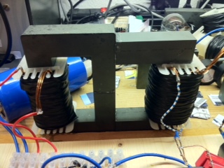
Establishing an LC tank with reasonable high Q
We have found that extracting energy from the system via the diode plug dampens the oscilalltion in the tank and of course changes the resonance frequency (more capacity seen by the coil at coil discharge). The input power required to maintain reasonably high oscilalltions rises as conventionally expected. The idea now is to fill this void (the energy we extracted) not with more energy from the DC power supply but let the ambient kick in (transformation of heat into electrical energy).- the core takes heat energy from the ambient (electron spin, movement whatever is reaccelerated)
- the core gets even hotter when the AC cap discharges into the coil (build-up of magnetic energy)
- we extract energy from the DC caps
- the core gets cooler while firing its magnetic energy into the caps
 |
With a 680nF cap attached to the coil we got at 11,6V/12,6A (146W) input wattage circulating power of 3.1kVAR in the tank. This corresponds to a Q = 42. We measured voltage and current in the tank and saw no indication of distortion in the current at all and thus no sign of saturation. We obviously need to raise the input power some more to get even higher currents.
We increase the AC cap to 1.5uF (1.2kV) and retune for resonance.
 |
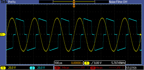
We have 11V/18.1A (199.1W) input wattage and get the following oscillations in the tank.
 |
We measure the voltage with a 10:1 voltage divider. This means we have a peak voltage of 710V in the tank. We measure the current over a 0.01 Ohm shunt. This means we have a peak current of 160A!?? We use 1.5uF and a frequency of 5.68kHz. This means the 1.5uF cap is charged up to 378mJ 11360 times per second (4.29kVAR). Still no current distortion and no noise that would indicate saturation of the core.
Could we really have reached 160A? The voltage of the cap is given by
 |
We then have
 |
 |
and thus
 |
Current measurement with the brass shunt obviously is not reliable in the kHz range (probably due to the skin effect). The resistance rose from 0.01 Ohm to 0.042 Ohm. At this resistance we burned 60W in the current shunt! :-( We therefore put four shunts in parallel to get 0.0025 Ohm. At 40A we then burn only 4W in the shunt. We have also drastocally shortened the cables.
 |
The two blue leads in the front carry no current but just connect the 10:1 voltage divider to the tank.
 |
Interesting! The phase shift is almost gone. The shunt - though reduced to 0.0025 Ohm - seems to be the only (greatest) resistance left in the circuit. We remove the shunt comletely.
At 10V (192W) and 1.5uF we get
 |
We get 680Vp oscillations in the 1.5uF tank at 5.732kHz. The energy in the cap at this voltage is 347mJ. The cap is charged up 11464 times per second. This corresponds to 3975VAR. We are still at Q = 20 with this coil.
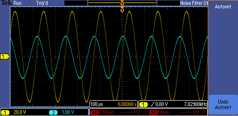
At 10V (183W) and 1.0uF we get
 |
We get 780Vp oscillations in the 1.0uF tank. The energy in the cap at this voltage is 304mJ. The cap is charged up 14060 times per second. This corresponds to 4277VAR. We now get Q = 23.4.
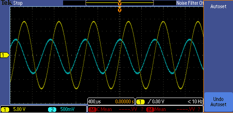
At 10V (149W) and with 0.5uF we get
 |
We get 900Vp oscillations in the 0.5uF tank. The energy in the cap at this voltage is 202mJ. The cap is charged up 19760 times per second. This corresponds to 4001VAR. We now get Q = 27.
We stick to 1.0uF since this gave the highest VARs.
Experimenting with the slit
We got the results above with lots of paper (a couple of mm) between the two U-cores. We replace the paper with small ferrit rings.
 |
At 1.76V/3.5A (6.1W) and with 1.0uF we get
 |
We get 150Vp oscillations in the 1.0uF tank. The energy in the cap at this voltage is 11.25mJ. The cap is charged up 13410 times per second. This corresponds to 150VARs We now get Q = 25.
It is very interesting to note that the input current rises with input voltage up to 3.4V/5.1A (this gives 250Vp in the tank) and then falls off again.
- 2V 3.9A 7.8W 175Vp 205VAR 26.3
- 3V 5.1A 15.3W 235Vp 370VAR 24.1
- 3.4V 5.1A 17.34 250Vp 419VAR 24.2
- 4V 4.7A 18.8W 260Vp 453VAR 24.1
- 5V 4.1A 20.5W 275Vp 507VAR 24.7
- 6V 3.6A 21.6W 280Vp 526VAR 24.4
- 7V 3.3A 23.1W 290Vp 563VAR 24.4
- 8V 3.0A 24W 295Vp 584VAR 24.3
- 9V 2.7A 24.3W 300Vp 603VAR 24.8
- 10V 2.5A 25W 300Vp 603VAR 24.1
- 11V 2.3A 25.3W 300Vp 603VAR 23.8
- 12V 2.2A 26.4W 300Vp 603VAR 22.8
at 10V (134W) and with 1.0uF
 |
We get 620Vp oscillations in the 1.0uF tank. The energy in the cap at this voltage is 192mJ. The cap is charged up 10840 times per second. This corresponds to 2083VARs. This corresponds to Q = 15.5.
Without the saturating element (rings) in the core we can increase the input voltage within the range of the power supply and get linearily rising output VARs.
At 10V (60W) we get 420Vp VARs = 1093 and Q = 18.
Thyristor approach
One of the MOSFETs steering the diode plug charge into the load died (was attached during tank experiments and got too much voltage). The idea was born to replace the two MOSFETs with MCD94 thyristors (2.2kV, 180A).
 |
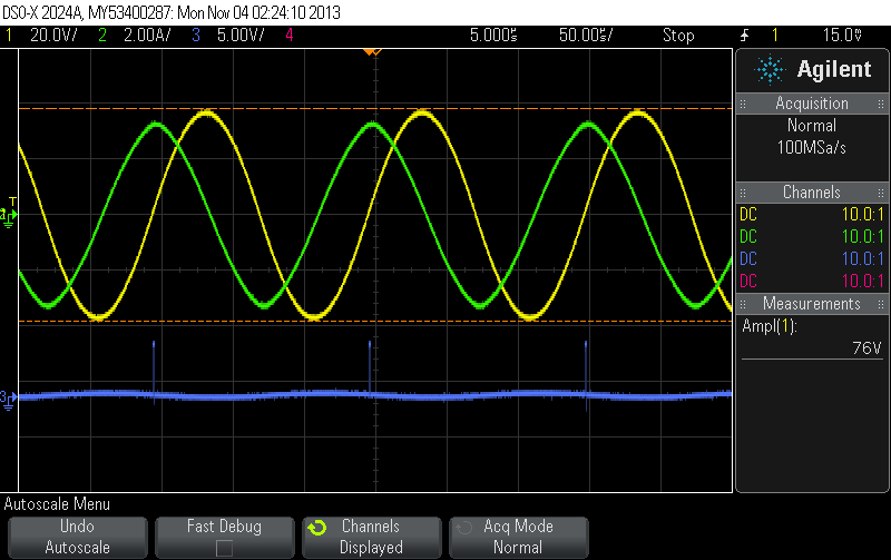
This turned out not to be an ideal approach. The yellow line shows the tank voltage. the blue line shows the voltage over the left DC cap.
 |
The thyristors obviously do not switch off in time and drag down the whole tank. We conclude that MOSFETs must be used.
MOSFET approach
We are back to using MOSFETs. The upper MOSFET got replaced. We are using a 2.2 Ohm 100W resistor for the load now.
 |
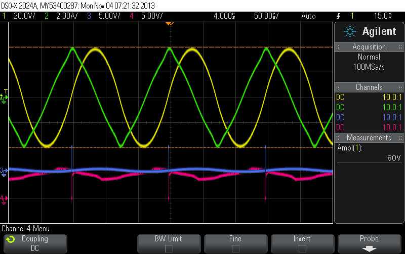
The scope shows better results now.
 |
The DC caps are charged with each cycle to tank voltage and fired into the load at the correct time. Discharging 75V in 300nF 11700 times per seconds corresponds to roughly 10W (a litlle less than the input wattage).
The upper control chip fried again! :-( We replaced the DC converter with a 05/12 (or use a 05/15 converter with a 7815). When the diode plug is active (DC cap MOSFETs are fired) the tank voltage does not rise beyond 75V.
Conclusion
Operating the tank in the linear region obviosuly leads to nothing but conventional behavious (COP < 1). But what if we create a tank with an even better Q (more turns of thick separated wire). If we reached a tank voltage of 2kV or more. Could this saturate the ferrit core and if so exhibit an anomalous effect? The effect we are looking for most likely occurs at a very specific frequency only, so a lot of cap values need to tried for a given coil.
HV setup
We have replaced the two MOSFETs with STW9N150 (1.5kV/8A). This MOSFET has a huge on resistance of 2.2Ohm but since we are looking for HV output now this is acceptable. We have replaced the load with a 1k resistor (100W). And we have added two GDTs to the peak detection circuit to delay the trigger to some higher voltage.
 |
With an input of 10,2V/7,3A (74W) we get the following now (measuring over 10:1 voltage dividers).
 |
The yellow line is the tank voltage reaching 300Vp now. The blue line is the voltage over the load (1k resistor).
At an input wattage of 14.8V/10A (148W) we get the following
 |
We are at 400Vp in the tank now. The energy we input to the system is delivered to the load. All components (MOSFETS,) stay cool. The load resistor gets hot as it should.
We go into the system with 16.1V/10.7A (172W) now and get
 |
The output wattage is only a little less than the input wattage. So the effiiciency is good but still under unity. :-(
Optimizing geometry (coupling, turns,)
We try a setup with a thick middle leg and weak coupling and try to optimize that for max Q.
 |
With no air gap on the left and right we get only 25Vp at 700Hz in the tank for 2W input wattage. We introduce 2 x 4 sheets of paper in the tank core. This gets us a much better Q. At 5V (2W) input wattage and 1.57kHz we get 140Vp. This corresponds to 15.4VAR and thus a Q = 7.7.
 |
We increase the input voltage. At 26V (28.5W) input wattage and 1.63kHz we get 440Vp and the current distortion we are looking for (saturation). 440Vp corresponds to 158VAR and thus to a Q of only 5.5!?
 |
With 12 sheets of paper in the tank core and 50nF cap attached we get at 32V (14.5W) and 7.829kHz
 |
This is 720Vp and with 50nF correspinds to 202 VAR and thus Q = 14.
New measurement row with 300nF and 60% duty cycle
We start with the following setup (no airgap in neiter core and approximately 2mm separation between the left and the right core).
 |
The best we can get is at 12V (7.2W)
 |
VAR = 0.11; Q = 0.01
We introduce 2 x 6 sheets of paper in the right core. This gets us a first reasonable result at 12V (3.2W):
 |
VAR: 8.64; Q = 2.7
We are tempted to introduce some more paper (2 x 12 sheets) into the right core. We get at 12V (2.7W)
 |
VAR: 24.2; Q = 9
We are still far away from an interesting Q, reasonable VARs and saturation. We increase the input voltage to 40V (26.6W) and retune.
 |
VAR: 150; Q = 5.6
We get more VARs with the higher input voltage but worse efficiency. :-(
Four leg setup
We try the following setup with no paper in the excitation core.
 |
We get at 45V (50W)
 |
VAR: 449; Q = 9
We put more turns on the excitation coil and less turns on the tank coil.
Ge get at 50V (2.1W)
 |
VAR: 38; Q = 18
Three leg setup
We try the followig setup.
 |
At 55V (15W) we get
 |
VAR 70: Q = 4.6
Interesting to note is that we approach the resonance frequency from above (higher frequencies). Once we have found the greatest amplitude we can reincrease the frequency again and see the peak voltage still rising until we reach the abov eshown maximum. If we increase the frquency some more the voltage breaks together to a very small value!?
At 55V (7.9W) with 200nF we get
 |
VAR 22; Q = 2.77
Att 55V (22.4W) with 300nF we get
 |
VAR 165; Q = 7.3
We put the U-core in the tank now and use the extension as the exciter. We also put lots of paper in the U-core to prevent to earlier saturation.
 |
At 50V (42.5W) we get
 |
VAR 944; Q = 22
We try to put even more paper into the tank to get more VARs before saturation occurs.
 |
At 50V (160W) we get
 |
VAR 4460; Q = 28
We try to raise the Q and the frequency (acustic noise) by winding a new tank coil of 17 strands of 1mm diameter copper wire. We start with 1uF attached.
 |
At 55V (150W) we get
 |
VAR 3897; Q = 26
This is actually worse than what we had with the other coil (not much) and the coil still gets hot (150W burned in the wire). We reduce the cap to 500nF.
At 55V (183W) we get
 |
VAR 4286; Q = 23.4
The coil gets hot quickly in spite of the thick wire (183W burned). We increase the capacity to 2uF and
at 47V (131W) get
 |
VAR 3402; Q = 26
Four leg setup
We try the following configuration masuring the voltage in the tank over a 10:1 voltage divider and having attached to the tank coil.
 |
Strange, we pulse the primary with 3kHz and get 9kHz oscillations in the tank (some harmonic)!?
 |
We have
 | |
 |
for an input wattage of
 .
.We now pulse the same setup with the frequency it wants (around 9kHz) and get
 |
 | |
 |
for an input wattage of
 .
.We increase the input voltage from 55V to 60V and get
 |
 | |
 |
for an input wattage of
 .
.
The coil wire gets warm after a couple of minutes. What does  mean? Where is this real power going to?
We now remove some paper from the tank core to allow slight saturation. This reduces the resonance frequency to 6kHz.
 |
 | |
 |
for an input wattage of

We can reduce the input voltage down to 48V once we are in the upper mode (jump resonance) and have tuned for resonance at 6.09 kHz before cuttoff occurs. The input wattage stays constant though (input current increases). Since the phase shift between voltage and current in the tank is less than 90° there is real wattage (heat loss) involved. This
 is much greater than the measured input wattage!? What could it mean?
Zero-crossing detection
We need a zero-crossing detection now and try the following appraoch.
 |
This circuit attached to the tank gives the following result.
 |
Not bad but probably not good enough! Ole Nielsen suggests a positive bias that allows to shift the bias horizontally.
 |
 |
Extraction by attaching a thief cap
At current/flux peak the core is saturated and the inductivity significantly reduced. Attaching a thief cap at this very moment for a brief moment might not destroy the resonance!? The thief cap is attached to the tank at current peak for a given pulse length (approximately 5% of the cycle). The cap is discharged into a load when disconnected from the tank.
 |
The upper part of the circuit generates the gate signal for the MOSFET that attaches the thief cap. The lower part generates the signal for the MOSFET that discharges the thief cap into a load. We discharge in the negative half of the cycle.
Att 55V / 57W input we get
 |
The blue curve represents the MOSFET gate signal that is supposed to attach the thief cap. The purple curve is supposed to discharge the thief cap into the load. Note, the the signals do not overlap. Thus the coil will never see the resistive load (just slightly increased capacity in the saturation phase).
We attach these two signals to MOSFETs. The overall setup looks as follows.
 |
The following scope shot shows what we get with this approach.
 |
The yellow (voltage) and green (current) curve show the tank (tank cap 630nF). The purple curve shows the signal that attaches the thief cap. The red line shows the voltage over the thief cap. It's charged up to 175V 5720 times per second. This corresponds to 55W. The input wattage is over 100W. The tank core gets hot pretty quickly! :-(
Extraction by coil shorting
We build a transformator with three legs, a pulsed coil on leg A, a resonated coil on leg B and another coil on leg C. The purpose of the tank (coil on leg B and external cap) is to generate high VARs in the tank core (up to 10kVAR). The coil on leg C is supposed to be shorted at sine wave voltage peaks.
 |
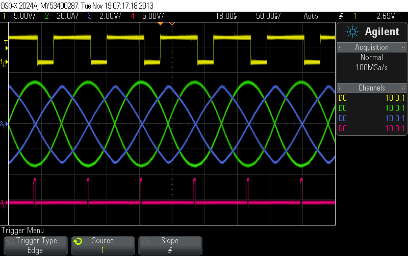
The following scope shot shows the voltage and current in the tank, the incuded voltage over coil C and the function generator pulses (purple) driving the H-bridge.
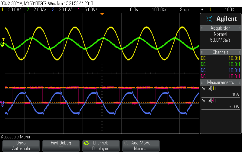 |
Since  and
and  we have a voltage sinewave peak whenever the rate of current change reaches a peak which is when current and flux cross the zero line. We want to short coil C at voltage sinewave peak. We try to get away without zero-crossing detection circuitry this time (gets nuts when we mess around with the inductivity) and make use of the function generator input signal instead, generate a shift with a one-shot and use another one-shot and a quarz-oscillator to generate the coil shorting pulses.
 |
The target cap should never be discharged below tank voltage level or releasing MOSFETs A has not the anticipated effect on the core (still shorted through FWBR and discharged target cap). We therefore check the target cap voltage with an adjustable 400:1 voltage divider and a Schmitt-Trigger. MOSFET C is only switched on during the non-pulses phase if the target cap voltage is high enough. This prevents a complete discharge of the target cap (keeps its voltage above tank peak voltage) which helps to secure a great felt difference for the core between MOSFETs A on and off states.
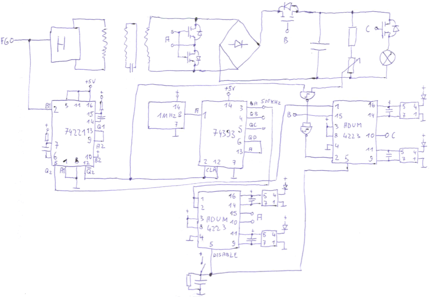
The two RCs connected to the One-Shot chip 74221 are chosen so that we get a couple of shorting pulses at sinewave voltage peak. According to the datasheet the resistor(s) should be between 2k and 100k and the cap between 10pF and 10uf. We are operating the tank at 6kHz and want to shift 90° of the cycle (40us).
 | |
 |
We choose 1nF for the caps and 50k for the external resistors. The counter 74393 is used as a divider of the 1MHz quarz oscillator. This allows us to easily choose between 500kHz, 250kHz,... for the shorting pulses.
A realization of the above circuit might look as follows:
 |
The following scope shot shows the generated signals for an input frequency of 12kHz (yellow).
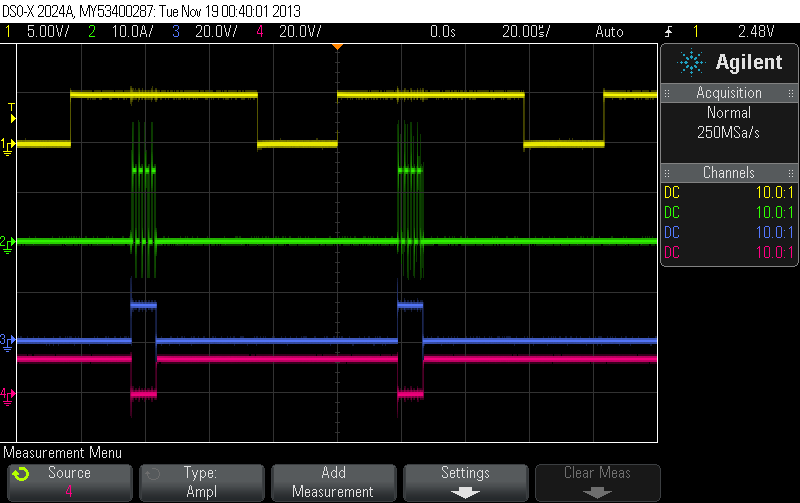 |
The green curve is the gate signal for the AC MOSFET switch, the blue curve the gate signal for the MOSFET B and the red curve for MOSFET C. We attach the MOSFETs and do a life measurement.
 |
We extend the active pulse width just a bit to get a shorting event from time to time.
 |
The pulses no longer appear at the right time. It looks like the tank phase shifts under load with respect to the incoming signal from the function generator!? :-(
Extraction by pulsed disconnection of the tank cap
We start by introducing an AC MOSFET switch into the tank that allows us to disconnect the tank cap. We can use low voltage MOSFETs with very low on resistance since these MOSFETs will never see the 400Vp of the tank, just the high current. We try two IRF3205 on each side of the AC MOSFET switch first.
 |
We no longer reach 400V and 40A (no saturation) and the MOSFETs get hot quickly. If the MOSFETS are conducting in bith directions when switched on the AC MOSFET switch should exhibit a resistance of 8mOhm. This should give us
 |
The heat of the MOSFET looks rather like 15W though. We add two more MOSFETs to the switch and heat sinks.
 |
We are almost back to 400Vp and the heat radiated away by the MOSFET heat sinks is moderate. We add two further MOSFETs to the AC switch (now four MOSFETs on each side) and finally get.
 |
We have 400Vpeak and 40Apeak at 6.69kHz. This corresponds to
 |
News
| 23.04.2023 | Cassiopeia 2.9.0 released |
| 05.10.2022 | Cassiopeia 2.8.3 released |
| 29.09.2022 | Cassiopeia 2.8.0 released |
| 08.07.2022 | Cassiopeia 2.7.0 released |
| 14.04.2021 | Cassiopeia 2.6.5 released |
| 10.02.2021 | Cassiopeia 2.6.1 released |
| 26.06.2015 | Word Processor Comparison |
| 24.06.2015 | Updated Documentation |
| 23.06.2015 | Cassiopeia Yahoo Group |
| 18.06.2015 | Advanced Data Security |
| 11.05.2015 | Cassiopeia Overview |
| 08.05.2015 | Exporting to files |
| 14.05.2013 | LaTeX and HTML Generation |
| 08.05.2013 | Example Paper released |
| 26.04.2013 | Co-editing in a workgroup |
| 16.04.2013 | Equation Editor Quick Reference |
| 12.04.2013 | Equation Editor |
| 04.04.2013 | Links and Bibliography |
| 01.04.2013 | Books |
| 30.03.2013 | Documents |
| 28.03.2013 | Simulations |
| 16.03.2013 | 2D Graphs |
| 10.03.2013 | Symbolic Algebra |
| 08.03.2013 | Getting Started |
| 07.03.2013 | Installation and Setup |
White Papers
| 13.10.2015 | 01 Writing documents |
| 15.10.2015 | 02 Using the equation editor |
Youtube
| 08.07.2022 | Installation & Getting Started |
| 14.04.2021 | Animating Wave Functions |
| 26.01.2016 | Keystroke Navigation |
| 22.10.2015 | Equation Editor Demo |
| 19.06.2015 | Equation Editor Tutorial |
| 10.06.2015 | Sections and Equations |
| 09.06.2015 | Getting Started |
| 09.06.2015 | Damped Oscillations |
| 29.05.2015 | Solving equations |
| 13.05.2015 | Privileges and Links |
| 19.06.2013 | Magnetic Field |
| 14.06.2013 | Creating Documents |
| 10.06.2013 | Vector Algebra |
| 30.05.2013 | Differential Simulations |
Contact
Smartsoft GmbH Advanced Science Subdiv.Support: support@advanced-science.com
