
 |
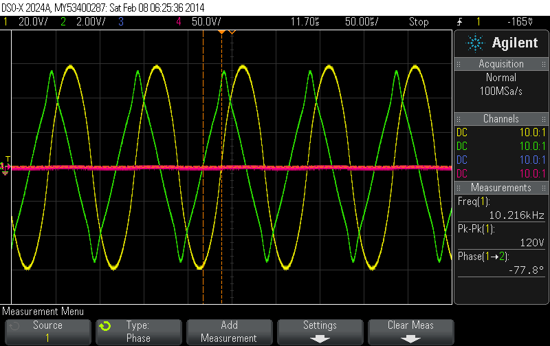
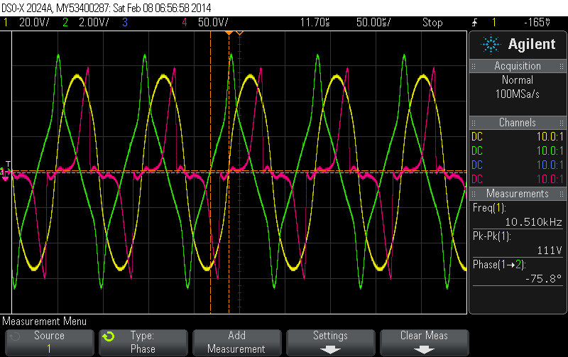
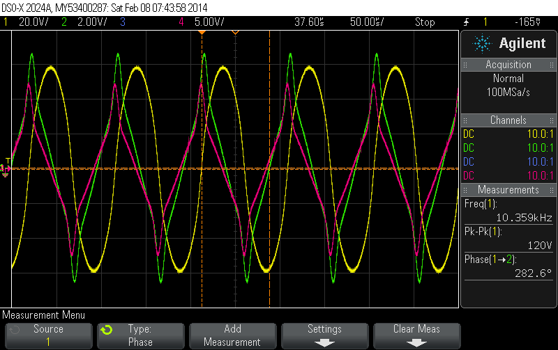
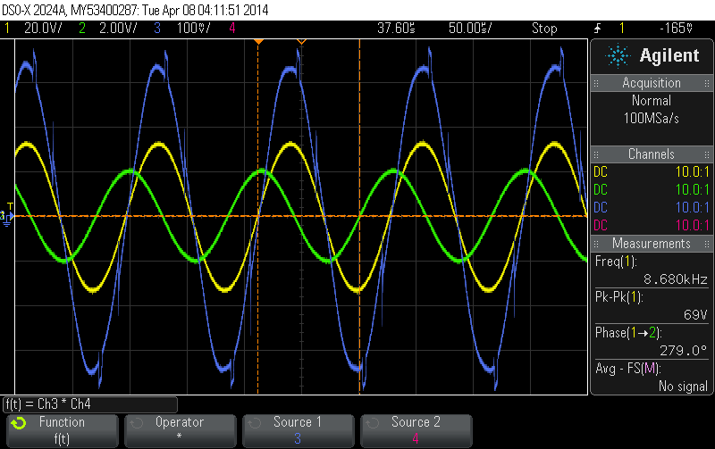
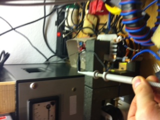
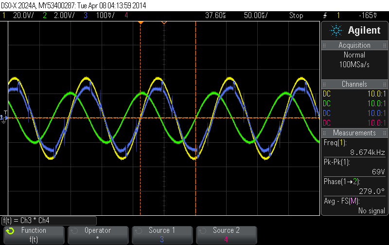
We would expect a phase of 90° between voltage and current. However, we measure only 77.8° instead and account this to the resistance of the wire. We let the rig run for a couple of minutes. The input wattage drops to 120W.
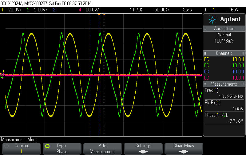 |
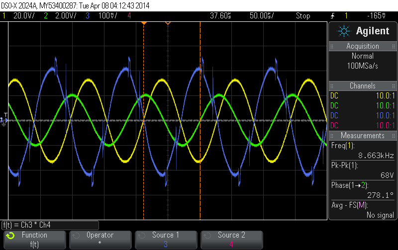
The phase shift is still the same though!? We let the rig run for a few more minutes. The input wattage drops to 112W.
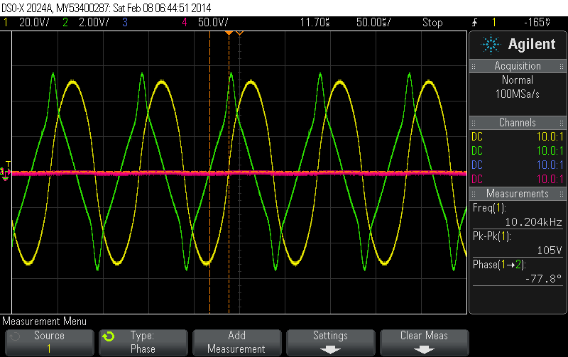 |
The tank core and coil wire are too hot to touch now. The phase shift nevertheless remains at 77.8°. But it seems that the tank voltage dropped significantly!?
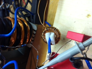
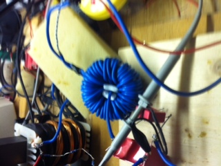
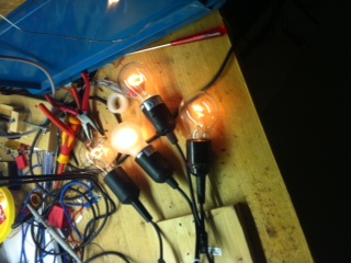
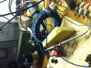
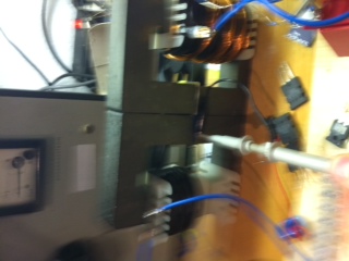
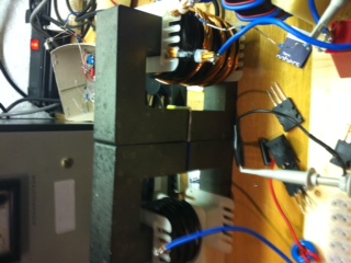
We put a torroidal core around the tank wire - one of the two wires that connect the tank coil to the tank cap - and connect a 220V/60W light bulb to that torroidal coil.
 |
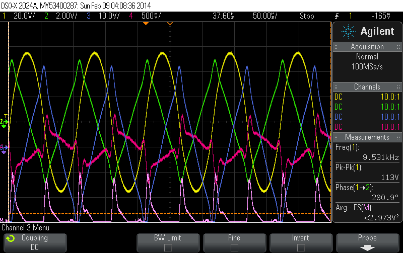
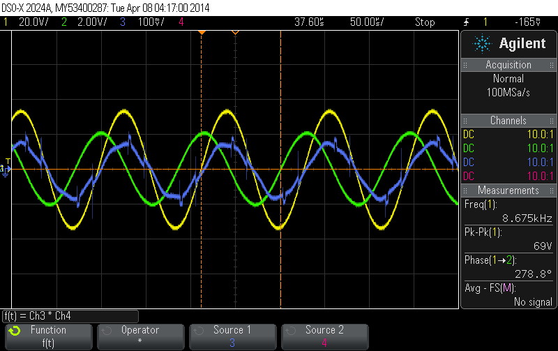
We increase the input frequency until we reach 160W input wattage again (the core is still pretty hot).
 |
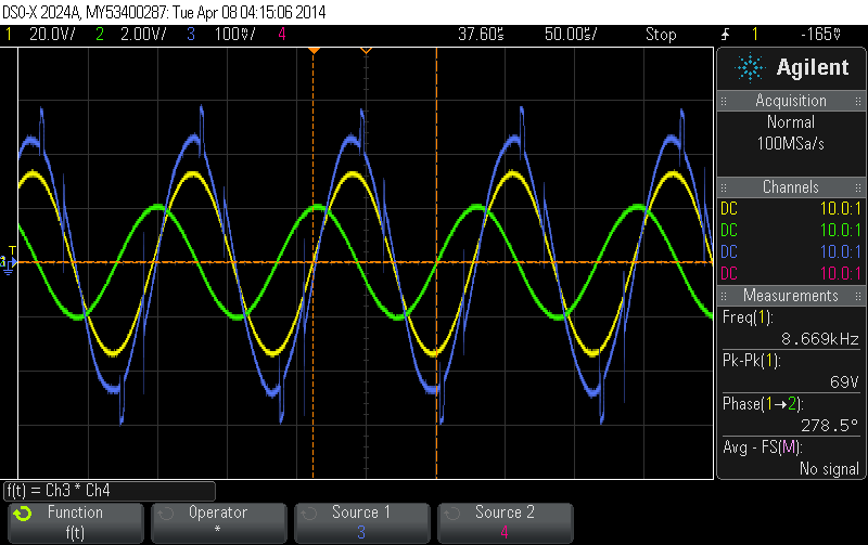
Interesting, we reach the spot (close to cut-off) at a significantly higher frequency with the load attached and with the core still being hot. The peak current almost reaches 70A! The red curve shows the voltage over the light bulb. Note, that the light bulb voltage rises rather slowly (probably somehow proportional to dI/dt) and drops off rapidly at some point.
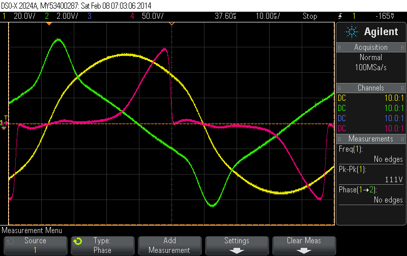 |
This happens significantly before the tank core goes into saturation. The tank core shouldn't have any effect on this anyway since our torroidal coil has its own core. Is this due to the torroidal core going into saturation (dI/dt still large but dB/dt --> 0)??
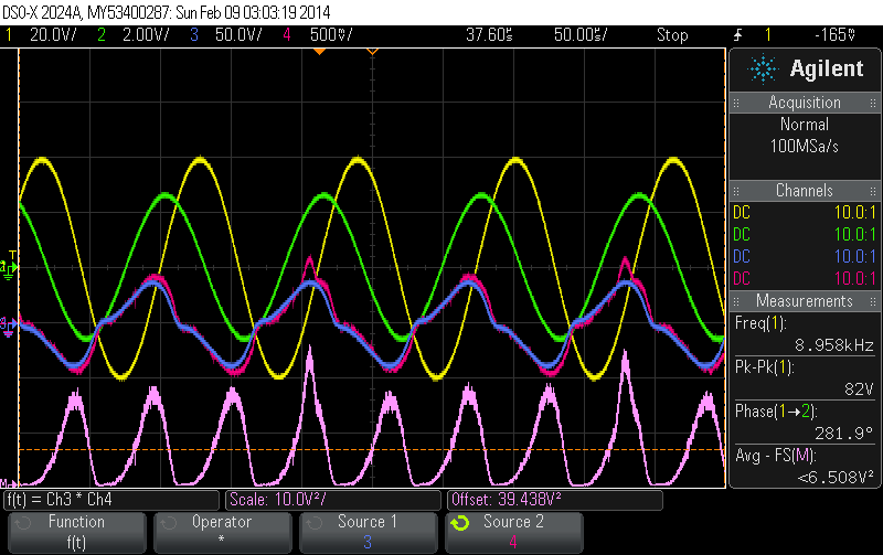
The light bulb is slightly lit (looks like 10W - 15W). We replace the 60W light bulb with a 1000W light bulb and repeat the experiment. We increase the frequency to the same value. This gives us an input wattage of 176W raising the tank volatge and current (VARs) a bit.
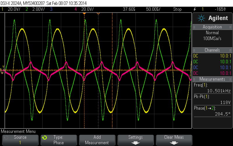 |
We observe the following:
- The output voltage (extraction coil) is essentally lower with the 1000W load (10Vp). This is probably due to the high impedance of the torroidal coil. We do not extract much energy from the system (very low voltage) and can easily establish highly non-linear resonance in the tank.
- The induced voltage peak is where dU/dt has a maximum, so proportional to the change of the charge density on the tank wire!?
 |
This gives us exactly the same with the 1000W light bulb attached to the extraction coil.
 |
Why is the voltage induced in torroidal coil not proportional to dI/dt and thus dB/dt but proportional to dU/dt (change of the charge density) and thus to dE/dt where E is the electrical field perpendicular to the conductor!?
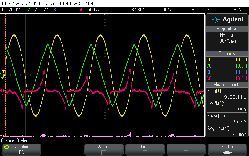
We attach the 60W light bulb again. We can no longer establish non-linear resonance. The 60W light bulb connected to the extraction coil kills the Q factor.
 |
The blue curve shows the light bulb voltage now and the red curve the current through the load. The M curve at the bottom gives the output wattage (65W). The input wattage for this experiment was 151W.
We put four 60W light bulbs in series and get
 |
 |
This load allows us to establish slightly non-linear resonance.
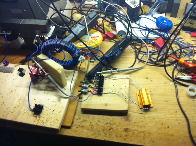
We try an even bigger extraction torroid (star gate type)
 |
and get
 |
We have an input wattage of 150W and extract 30W with the extraction coil. We can easily attain highly non-linear resonance even with 30W being extracted.
We use a 100W 1K resistor for the load (rather stable resistance and very low inductance) now
 |
and get mainly the same result!
 |
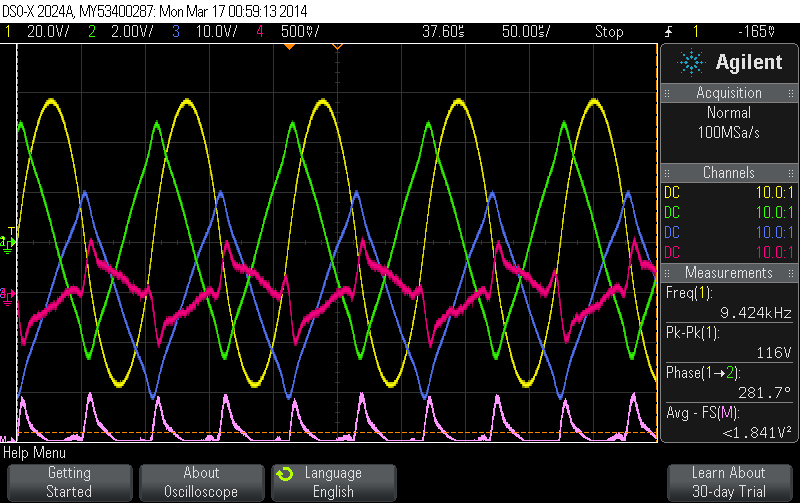 |
The induced voltage (blue) is in the 200Vp range and has its maximum where the tank current has its peak!? The current trough the linear load has the same weird form!? Note that we have stll positive current where the induced voltage is already negative. This indicates that current lags voltage significantly. This can only be caused by the huge inductance of the star gate coil!?
Conclusion: The load resistance determines the wattage extracted from the system. A too small resistance causes a very low output voltage and thus small output wattage. A too high resistance limits the current. The optimal extraction resistance (for getting the highest output) would be one that is identical to the impedance of the extraction coil (at 8.9kHz). The LCR-meter shows an inductivity of 12.2mH for the extraction coil. At 8.9kHz this would correspond to an impedance of
 |
However, we have seen that the closer we get to this optimal value (for power exctraction) the more the Q of the tank is destroyed. We need to stay far away from this value to still see the latching effect and non-linear resonance in the tank. This is discouraging from a FE point of view. However, there is one important point to note. The induced voltage in the extraction coil is - as long as we stay far away from the above mentioned optimal impendance - proportional to
 where E is the electrical field perpendicular to the current carrying conductor. This is not expected at all. Usually we would argument that
 |
 |
we would expect the induced voltage to have its maximum where dI/dt has its greatest value!? We have highly non-linear current in the tank. It's therefore difficult to tell where in the interval this is. It seems the current changes with a almost constant dI/dt for most of the time. However, it comes as a surprise that the induced voltage and the tank current have the same phase angle!?
Magnetic field around the tank core
We measure the magnetic field around the tank core with a wire loop. The yellow curve is the tank voltage, the green teh tank current and the blue the measured voltage in the wire loop.To the right of the middle leg (top):
 |
 |
To the right of the middle leg (bottom):
 |
 |
The induced voltage changes direction when going from top to bottom. An explaination for that would be that the EMF is mainly induced by the wire part close to the slit. It seems that massive aether winds leave the core there.
We interestingly enough also measure significant EMF on top of the core in the center. It seems that the aether winds don't stay completely contained in the core but propagate vertically through the core and leave it to some extend even without a slit nearby.
 |
 |
We position the wire loop next to the slit again and get significant EMF.
 |
 |
Even a couple of centimeters away we still measure significant EMF.
 |
 |
News
| 23.04.2023 | Cassiopeia 2.9.0 released |
| 05.10.2022 | Cassiopeia 2.8.3 released |
| 29.09.2022 | Cassiopeia 2.8.0 released |
| 08.07.2022 | Cassiopeia 2.7.0 released |
| 14.04.2021 | Cassiopeia 2.6.5 released |
| 10.02.2021 | Cassiopeia 2.6.1 released |
| 26.06.2015 | Word Processor Comparison |
| 24.06.2015 | Updated Documentation |
| 23.06.2015 | Cassiopeia Yahoo Group |
| 18.06.2015 | Advanced Data Security |
| 11.05.2015 | Cassiopeia Overview |
| 08.05.2015 | Exporting to files |
| 14.05.2013 | LaTeX and HTML Generation |
| 08.05.2013 | Example Paper released |
| 26.04.2013 | Co-editing in a workgroup |
| 16.04.2013 | Equation Editor Quick Reference |
| 12.04.2013 | Equation Editor |
| 04.04.2013 | Links and Bibliography |
| 01.04.2013 | Books |
| 30.03.2013 | Documents |
| 28.03.2013 | Simulations |
| 16.03.2013 | 2D Graphs |
| 10.03.2013 | Symbolic Algebra |
| 08.03.2013 | Getting Started |
| 07.03.2013 | Installation and Setup |
White Papers
| 13.10.2015 | 01 Writing documents |
| 15.10.2015 | 02 Using the equation editor |
Youtube
| 08.07.2022 | Installation & Getting Started |
| 14.04.2021 | Animating Wave Functions |
| 26.01.2016 | Keystroke Navigation |
| 22.10.2015 | Equation Editor Demo |
| 19.06.2015 | Equation Editor Tutorial |
| 10.06.2015 | Sections and Equations |
| 09.06.2015 | Getting Started |
| 09.06.2015 | Damped Oscillations |
| 29.05.2015 | Solving equations |
| 13.05.2015 | Privileges and Links |
| 19.06.2013 | Magnetic Field |
| 14.06.2013 | Creating Documents |
| 10.06.2013 | Vector Algebra |
| 30.05.2013 | Differential Simulations |
Contact
Smartsoft GmbH Advanced Science Subdiv.Support: support@advanced-science.com
