
 |
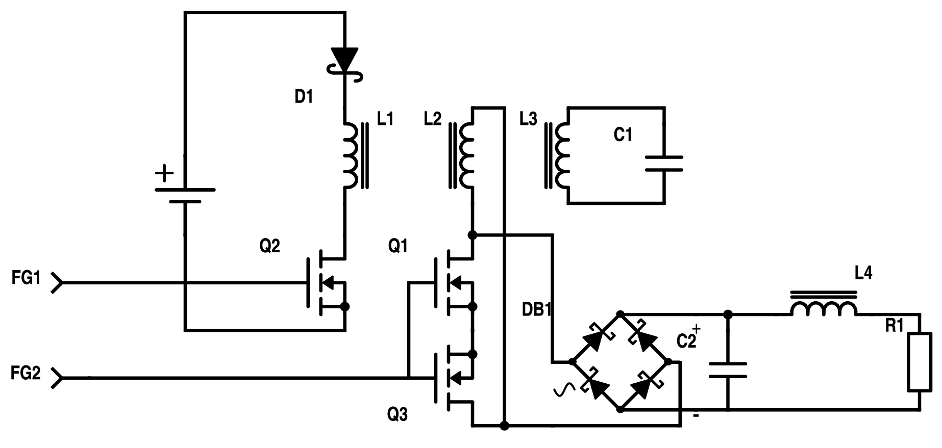
FG1 generates a square wave with 25% ducty cycle in the 8kHz range pulsing the tertiary coil into resonance. The secodary is shorted with a 20% duty cycle square wave in the 80kHz range. The idea is that the CEMF and fly-back pulses through the FWBR charge the target cap with hardly reflecting back ont the primary (input power). The probability of reaching this objective is higher if ferro-resonance can be achieved.
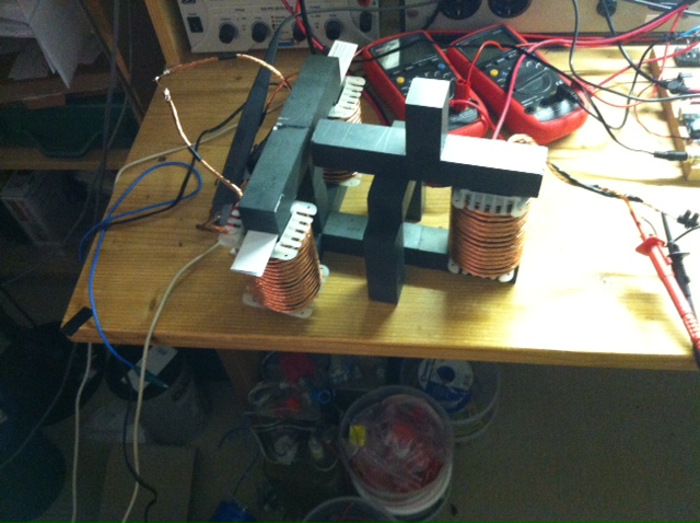
We try to get the tank into resonance first. Pulsing with a single MOSFET (duty cycle 25%) does not give us enough power in for reasonable VARs. We therefore switch to a H-Bridge pulsing the right coil (L1). The double tank coil(s) in series on the left (L3) are attached to 200nF.
 |
This gives us
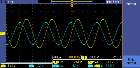 |
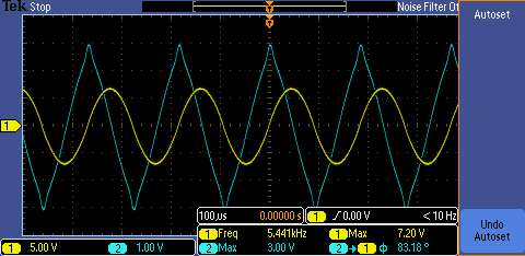
- (yellow) tank voltage (1020V peak)
- (blue) tank current (16A peak)
This is extreme VARs. The H-Bridge MOSFETs stay cool, so do the coils. Where is the input wattage going to? We have reached the liit of the P6022 current probe and switch to a Chauvin Arnoux E3N.
We remove the air gap between the pulsing primary and the tank core try again.
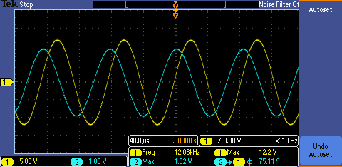 |
- (yellow) tank voltage (1220V peak)
- (blue) tank current (19.2A peak)
Increasing the input wattage and thus the VARs in the tank any further crashes the whole thing (probably HV break throughs from the tank coil to the core).
We replace the 200nF with 1uF to get lower voltage and higher current and end up with
 |
- (yellow) tank voltage (720V peak)
- (blue) tank current (30.0A peak)
We replace the 1uF cap with 500nF and try again.
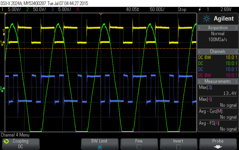 |
- (yellow) FG singal feeding the H-Bridge
- (blue) voltage over the pulsed primary
- (green) voltage over L2 (11 turns)
 |
- (yellow) tank voltage (1110V peak)
- (blue) tank current (35.6A peak)
News
| 23.04.2023 | Cassiopeia 2.9.0 released |
| 05.10.2022 | Cassiopeia 2.8.3 released |
| 29.09.2022 | Cassiopeia 2.8.0 released |
| 08.07.2022 | Cassiopeia 2.7.0 released |
| 14.04.2021 | Cassiopeia 2.6.5 released |
| 10.02.2021 | Cassiopeia 2.6.1 released |
| 26.06.2015 | Word Processor Comparison |
| 24.06.2015 | Updated Documentation |
| 23.06.2015 | Cassiopeia Yahoo Group |
| 18.06.2015 | Advanced Data Security |
| 11.05.2015 | Cassiopeia Overview |
| 08.05.2015 | Exporting to files |
| 14.05.2013 | LaTeX and HTML Generation |
| 08.05.2013 | Example Paper released |
| 26.04.2013 | Co-editing in a workgroup |
| 16.04.2013 | Equation Editor Quick Reference |
| 12.04.2013 | Equation Editor |
| 04.04.2013 | Links and Bibliography |
| 01.04.2013 | Books |
| 30.03.2013 | Documents |
| 28.03.2013 | Simulations |
| 16.03.2013 | 2D Graphs |
| 10.03.2013 | Symbolic Algebra |
| 08.03.2013 | Getting Started |
| 07.03.2013 | Installation and Setup |
White Papers
| 13.10.2015 | 01 Writing documents |
| 15.10.2015 | 02 Using the equation editor |
Youtube
| 08.07.2022 | Installation & Getting Started |
| 14.04.2021 | Animating Wave Functions |
| 26.01.2016 | Keystroke Navigation |
| 22.10.2015 | Equation Editor Demo |
| 19.06.2015 | Equation Editor Tutorial |
| 10.06.2015 | Sections and Equations |
| 09.06.2015 | Getting Started |
| 09.06.2015 | Damped Oscillations |
| 29.05.2015 | Solving equations |
| 13.05.2015 | Privileges and Links |
| 19.06.2013 | Magnetic Field |
| 14.06.2013 | Creating Documents |
| 10.06.2013 | Vector Algebra |
| 30.05.2013 | Differential Simulations |
Contact
Smartsoft GmbH Advanced Science Subdiv.Support: support@advanced-science.com
